|
While small in cost, seals are often
one of the most important components in any product. A seal must
be carefully designed and produced to ensure superior
performance of the product in which they are used. This section
provides the technical data necessary for proper seal design and
selection, including how to determine groove dimensions, cross
sectional squeeze and other necessary criteria.
All sealing applications fall into one of two categories - those
in which the seal or sealed surface moves, and those in which
the seal is stationary:
A seal that does not move, except for pulsations caused by
cycle pressure, is called a static seal. Examples include the
face seal in an end cap, seals in a split connector, and seals
between two stationary members.
|
 |
Dynamic seals are those that are subjected to movement. These
are further defined as rotary (stationary seals exposed to a
rotating shaft) or reciprocating (seals exposed to linear
motion). Rotary seals and reciprocating seals require different
design, dimensioning and material selection for proper function.
Factors to Consider
in Seal Selection
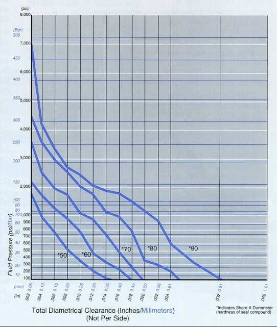
Proper seal design begins with careful consideration of the
sealing application. Appropriate material hardness, for example,
is determined by the friction and pressure to which the seal
will be exposed, as well as the cross-sectional dimensions of
the seal. Other key factors include temperature range, adjacent
surfaces, and media. (Keep in mind that the environment may
differ from one side of the seal to the other.) Established
standards may also dictate which materials may be used.
Friction
The functional life of a seal is determined primarily by the
level of friction to which it is exposed. Key factors
contributing to friction include rubber hardness (the standard
compound for most seal applications is 70 durometer Shore A
hardness), surface finish, temperature extremes, high pressure
and the amount of squeeze placed on the seal.
The use of "slippery rubber" compounds can help lessen
friction and improve seal life. Surface coatings and seal
treatments such as PTFE and molybdenum disulfide are also used
to reduce seal friction.
Please contact us early in the design process. Given the number
of variables involved, it is impossible to accurately calculate
seal friction in terms of force-per-area. By the same token,
there are no quick and easy "standard rules" for
specifying the appropriate seal material or coating solution.
The close working relationship that exists between our design
engineers and staff chemists means we can provide you with the
optimum in part design and material selection.
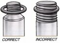
Surface Finish
Shorter than expected seal life is generally the result of too
fine a finish on either the rod or the cylinder bore. A highly
polished (non-porous) metal surface does not retain the
lubricant necessary to control friction, whereas a rough or
jagged surface will abrade the seal and lead to early seal
failure.
In order to avoid these problems, we recommend an ideal surface
finish of 20-24 RMS (.5-.6 +/-m), with an acceptable range of
20-32 RMS (.5-.81 +/-m). The surface finish should never be finer
than 16 RMS (.4 +/-m). We further recommend the use of a
finishing tool called a Flex Hone, from Brush Research
Manufacturing Co., Los Angeles, CA. The Flex Hone creates a
cross-hatched finish that provides the ideal combination of
smoothness and lubricity.
Roller-burnished and mandrel-drawn finishing, on the other hand,
should be avoided wherever possible. While these methods assure
a very true diameter, they also result in a surface finish well
beyond the recommended range.
Roller burnishing can be employed, however, prior to flex honing
to ensure maximum dimensional accuracy and an optimal sealing
surface.
Ease of Installation
|